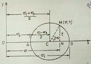
Mohr Stress Circle When an Element is Subjected To Normal Stress Only
For drawing the Mohr stress circle, the normal stresses are represented along the x-axis and shear stresses along the y-axis. The Mohr stress circle is drawn, as shown in the figure, with its centre at a distance of ( 𝞼1 + 𝞼3)/2 and ( 𝞼1 – 𝞼3)/2.

Where 𝞼1 & 𝞼3 are the major and minor principal stresses respectively. A point M on this circle, subtending an angle 2α at the center C, will represent the stresses on the plane which was making an angle α with the major principal plane.
In other words, the coordinates of this point would be equal to shear stress (𝞃 )and normal stress (𝞼).
Read Also:
Mohr-Coulomb Failure Theory(Criterion)